We’d better not risk another frontal assault, that rabbit’s dynamite!
We need to design the rest of the power supply circuitry. This should be relatively simple, other than the complication discussed earlier, the need for separate B+ supplies for the output stage and driver. To be fair, the raw supplies I’ll outline are OK, but just OK. They are quite ad hoc and oriented toward oddball parts I just happened to have in my various coffee cans. You can do better, but this is at least a good starting point and will do the job. The critical item is the output stage screens, and our regulator tightens that point up nicely, making raw supply design much less critical. This is my version of the raw supply:
B+ and heaters were addressed with the power transformer taken from the same SCA35 that was the output transformer donor. This transformer is still available as a new item under the trade-name “Dynaclone.” And of course it’s not critical- any transformer or transformers with similar ratings will work fine. Note the series connection of the two heater windings- you need to verify the phasing of the two windings.
On the primary side, I’ve become lazy and started using complete Power Entry Modules in my projects.
These contain an IEC power connector, a crude line filter a switch, and a fuse in a nice convenient package that only requires a rectangular hole for mounting. Corcom is a standard brand, but there are many others. An inrush current limiter will be a net positive for reliability. The device I used was approximately 100 ohms cold, and something under 5 ohms when warm.
The output stage B+ supply is an utterly conventional full wave rectified, CLC filtered supply. I used fairly prosaic parts here, but high speed diodes don’t cost very much these days and can certainly be used here to good effect. In later builds, I started using UF4007, which could not hurt in the noise department. For added reliability, I later changed the single rectifiers to a series pair, each with a 470k voltage equalizing resistor across it. The electrolytic caps should be 105°C rated; the 100uF values are not excessive. A polypropylene cap in the second position would be a worthwhile upgrade. The choke is also rather non-critical- a Dynaclone C354 is inexpensive and works well.
Grounding is critical- the circuit between the rectifiers and the transformer center tap carries high ripple currents and tapping into more than one point here will cause hum and buzz problems.
Return the transformer CT directly to the electrolytics’ negative terminals and attach the far end of the signal ground bus exactly to that point.
The sharp-eyed will note that this supply totally abuses the maximum plate voltage rating of the EL84. This was the case for every SCA35 that Dynaco made. I will look innocently in the air, clasp my hands behind my back, and slowly walk away, whistling a tune…
The supply for the driver stage is even more non-critical; we basically just need a fairly quiet 350-400V at low current (10mA or so).
For the prototype, I had a 270V transformer left over from another project, so it was pressed into service with a full wave bridge rectifier and another CLC filter. The version shown here uses an Allied 6K3VG transformer (apparently made by Hammond), which gave a voltage that was much too high. The funny wiring between the heater windings and the primary is set to buck the input voltage, thus reducing the voltage at the secondary. A more felicitous transformer choice would sidestep the issue.
Regulation of the driver stage supply is not critical- the stage draws only a few milliamps and if the voltage wanders around over the course of time, that doesn’t much affect the operation of the circuit. The choke I used was a 35Hy 15mA unit, but there’s a lot of latitude here, too. Tying the phase splitter and input stage B+ feeds together is useful for stability purposes- resist the temptation to separate the supplies.
As mentioned earlier, the heaters are floated up to 20% of the B+ value by the voltage divider. This insures that the heater to cathode voltage ratings of both sections of the 12AT7 are within rated limits. Note the common-mode bypass caps, which will help keep the heaters from coupling rectifier switching noise right into the cathodes of the input tube. An improvement would be the addition of a common-mode choke between the transformer and the bypass caps. Go for it if you’re worried about that sort of thing; without it, the amp still managed to keep the high frequency hash well below -100dB.
“I think I’ll go for a walk…”
It’s time to consider the build itself. Being that this is a rather classic topology, there is nothing unusually critical. Attention must be paid to grounding and heater wiring to minimize noise. Grounding should be done with the usual care to avoid loops and unintentional feedback. In my particular construction, I used a bus system consisting of a heavy copper wire starting at the input terminal grounds and terminating at the power supply common. All grounds are connected along this bus and nowhere else. The chassis ground should be placed right at the input terminals; a ground lift arrangement may be necessary if the amp causes any hum when external components are connected. This can be as simple as a 33R resistor separating the system ground from the chassis; another approach (perhaps a better one) is to use paralleled diodes, with one reversed with respect to the other. This limits any loop voltage to 0.7V in either direction, and if there is a mains fault, the diodes will tend to fail as short circuits, blowing the fuse rather than electrocuting the user. In either event, the ground wire from the power cord (safety ground) should be firmly and permanently attached to the chassis near the power entry. There should be no other connections to the chassis or hum will result.
Heater wiring should be tightly twisted, dressed to hug the chassis, and where possible, tucked into the corners and edges of the chassis. As a practical matter, it is generally best to do the heater wiring before anything else; without tubes inserted, apply power and measure the AC voltage between the outer two leads (i.e., the two that aren’t grounded). If it’s something like 15V, you’re cool. If it’s something like zero, remove power, reverse one of the sets of heater leads, then check again.
Insert the tubes into their sockets, turn on the power, and make sure everything lights up properly. Power down and remove the tubes before proceeding with the rest of the wiring!
Speaking of wire… I am not the religious type, but Teflon-insulated silver wire solders quite beautifully with silver-bearing solder.
I recommend it. Use wire with good (600V or better) insulation. Resistors and caps are also fetish object among audio neurotics. I’ll risk drawing their scorn by noting that I used carbon composition grid leak resistors because of their very low inductance. Plate and cathode resistors are metal film, though wirewound would also do very well. Use at least 2W for the first stage plate and the phase inverter plate and cathode resistors; I had some very nice surplus WE-MEPCO units that are quiet and stable, but I’ve also used some no-name metal oxide resistors that worked very well. The phase splitter resistors should be tightly matched; so should the output stage grid leak resistors which form part of the phase-splitter load.
Capacitors are even more a matter of religion. You can’t go wrong using good quality polypropylene and foil; my favorites are Wima FKP. Fetishists can go exotic and use Teflon, silver, copper, whatever the Material of the Month is. Paper caps suck, sorry.
The feedback resistor should be attached directly to the top of the input tube’s cathode resistor. Feedback is brought in via a shielded cable, the center conductor of which is connected to the feedback resistor. The shield should be attached directly to the bottom of the input tube’s cathode resistor. This ensures that the feedback is applied and referenced to the right spots.
I’ve tried three different output transformers here, Dynaco relics from an SCA-35, some classic UTS LS iron, and some lovely transformers from James in Taiwan (the cover shot is an amp made with the James iron).
There are a lot of alternatives out there at a variety of price points; what you want is something rated 15W or better, 8k plate-to-plate primary, secondary to match the speakers you want to drive. The only circuit modification needed for output transformer substitutions may be the RC compensation network shunting the input tube plate load. The tuning procedure is described in detail in Morgan Jones, “Building Valve Amplifiers,” and some excellent general discussion can be found in Norman Crowhurst, “Understanding Hifi Circuits.” The values I give here work fine with the James and original Dynaco transformers.
If you want to optimize these values or adapt them for another output transformer, an oscilloscope, an 8 ohm dummy load, and a 1kHz square wave are your friends; set the values so that there is minimal ringing on the leading edge of the square wave. Some overshoot is acceptable as a compromise to keep the bandwidth reasonably high.
Disconnect the load and see if the amp breaks into oscillation. If it does, make the compensation a bit heavier by lowering the resistor value and/or increasing the capacitor value. Reconnect the load and parallel it with a 4uF capacitor. Again, ensure that the amp does not oscillate; you will see some overshoot, or if you already had some, it may increase a bit This is perfectly acceptable so long as the period of the overshoot corresponds to 50kHz or higher. If you see no ringing whatever, feel free to decrease the capacitor and/or increase the resistor until you start seeing overshoot; this will extend the bandwidth a bit, and may well be possible with nicer, more modern output transformers. Double-check check no-load and capacitive load stability.
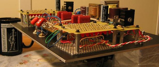
The circuit is simple enough that it can easily be constructed on a PCB, perfboard, or point-to-point using terminal strips or terminal boards. If there is sufficient interest, a PCB will be made available.The screen regulators and LED arrays were put on actual PCBs; I like the modular approach for servicing, upgrading, ease of construction, and the ability to mix and match modules between different projects.
I like lots of airflow; the prototype was built on the discarded cage of an old Stereo 70.
If you use a solid chassis, make an oversized cutout for the output tubes, then mount the sockets on a sub-panel of perforated aluminum or steel. For some real fun, you can mount a perf board or PCB containing the LED arrays underneath the output tubes, which provides a rather spooky bottom lighting. Doubtless someone with a better esthetic sense than mine will come up with some lovely patterns or lighting effects.
Some of the details of my nicer build; the top view:
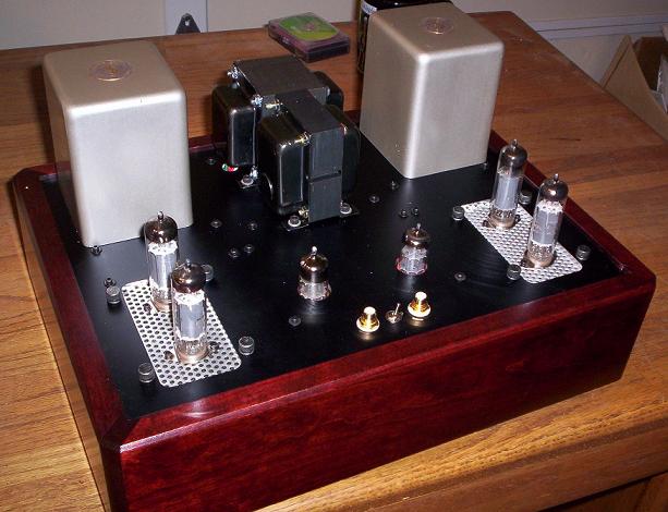
(sorry for the background)
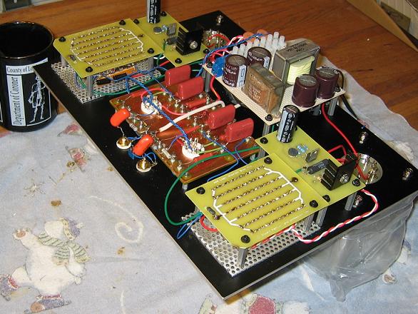
And upside-down with the skirt removed:
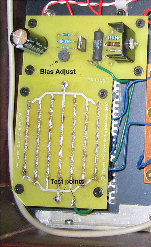
Close-up of the regulator and the LED array board:
And a side view of the patient to show how I bottom-mounted the LED arrays:
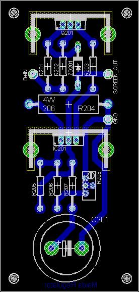
The Maida regulator board:
And the Front Panel Express file for the top plate can be downloaded from here:
www.syclotron.com/rldtopplate.fpd
Read back through the text for startup and adjustment hints. Basically, you want to wire up heaters and power supply primary first, check the wiring, then put in the tubes and power up. If they all light OK, power down, remove the tubes, and wire up the rest of the power supply. For raw power supply checkouts, I take two precautions: first, I use a dummy load to draw some small current from the supply output (and bleed it quickly on shut-down, a 33k/10W wirewound served for me), and then I connect a 60W lightbulb in series with the primary. If all is wired OK, at power on, the bulb will get bright, then dim quickly. Voltages might be somewhat low, depending on the dummy load.
If the bulb doesn’t dim in a second or two, power down and look for a bad component and/or a mistake. Assuming all looks well, we can connect the regulators, load them down with a 47k/5W dummy load, and verify that they regulate. Turn the regulator(s) output(s) down to minimum output voltage. If this checks out, power down, unplug, and go have a drink while the bleeders bleed. I don’t know about you, but the first power-on scares the shit out of me and I need a few shots to steady my nerves…
The signal circuitry can now go in place. For checkout, just plug in the driver tubes, not the outputs. If you’ve done your job well, the plate voltage on the input tube will be 120V or so, cathode voltage of the inverter a volt or two above that, and the inverter plate voltage about 250V. Power down, then plug in the output tubes. Make certain the screen regulator trimpots are still set for minimum voltage. Connect a power resistor with the same resistance as your speakers’ nominal impedance (e.g., 4, 8, or 16 ohms). Connect an oscilloscope across the power resistor. Connect a millivoltmeter across the 1 ohm cathode resistors, then power on. The LEDs should light after 10 seconds or so. If the millivoltmeter reads over 80mV or you see any oscillation, power down and check your work. If it stabilizes at a lower value, wait about 10-15 minutes, then slowly and carefully raise the regulator voltage until you see 85mV across the cathode resistor. Verify that the regulator voltage is below 300V, then pour another drink and play some music. The phasing of the output transformer primary is critical- if the circuit oscillates with the feedback loop connected, power down, discharge caps, and switch the primary leads between the output tubes. The compensation network can now be adjusted using the procedure discussed before.
“I want to sinnnngggg…”
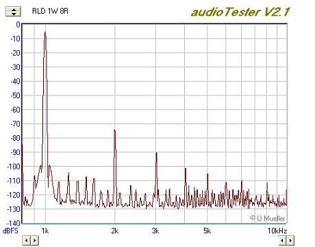
Built as described here, my version of this amp gave a power out at clipping of 18W/channel into an 8 ohm dummy load. At 1W, the 1kHz total harmonic distortion measured less than 0.02%, dominated by 2nd and 3rd. The distortion smoothly rises with power; at 5W out, THD was 0.05%, with 3rd at -70dB, the other harmonics below -85dB. The amp is stable without a load (though I wouldn’t recommend this!) and with heavy capacitive loads.
With a damping factor of 4, it’s a good match for many mini-monitors, small ESLs, and full range units. It is probably not the ideal match for power-hungry low impedance speakers, speakers with flabby bass that need a low source impedance to stretch out the cellulite, or real current-hogging panel speakers like Magneplanars. Despite this, the amp did surprisingly well with power-craving Acoustat 1+1s, albeit at less than ear-splitting levels. With some home-brew MTMs and NHT Super Zero minis, the amp was in its element.
The quality that is striking is the muscularity of the sound- you will not believe that this is a low power amp. The secret to this quality is the attention paid to overload recovery time- using a signal generator that alternated levels between 3dB below clipping and 3dB above clipping, the total absence of blocking or choking up was easy to see on an oscilloscope screen. And that’s evident in listening- things don’t go all congested when the music gets complex and loud. One neat feature is a built-in clipping indicator- the LEDs’ brightness goes up noticeably when the amp clips. It’s remarkable to see them flashing, yet have the amp still sound clean.
Removing the feedback loop increases the gain and the output impedance. The latter ends up at something over 50 ohms, which is a nice source impedance for the current drive concepts of Mills and Hawksford, as elaborated on by Nelson Pass. Because of the moderate feedback, the open loop distortion is still quite low, under 0.3% THD at 1W/8 ohm/1kHz. The distortion starts getting a bit uglier at 20 Hz and below, but why in the world do you want to run a little tube amp that low?
Although the raw supply section is crude, attention to grounding and lead dress resulted in a very, very quiet unit. Hum and buzz were inaudible even in near-field listening; golden ears might note the black velvet background from which the music stands in sharp relief. Or something like that.
Acknowledgements:
As usual, the crew at diyAudio.com was a great resource, with particular props to pinkmouse for board design and rdf for interesting discussions and suggestions on LED distortion and general nit-picking. Pinkmouse did the PCB designs. Morgan Jones was kind enough to offer some very helpful criticism, not to mention setting me down the LED path in the first place. John Broskie’s encouragement and creative riffing on the design helped me greatly in solidifying many of my choices. The input from these guys made this a much better article. Joel T’s Paint schematic symbols remain extremely useful for software-inept guys like me. Daan van Egmond turned me on to the Agilent LEDs, for which I’m eternally grateful. And last but not least, John Sprow was kind enough to look past the rough exterior of the prototype and fund a mini-production run, which forced me to attend to details and build something visually acceptable.
Some Updates:
Since I wrote this article a decade ago, I’ve made a few improvements. I’ll end up writing them all up at some point, but the biggest one was to bring the plate voltage much higher (now 550V), reduced the idle current to about 25mA per tube, and increased the plate to plate load by moving my speakers to the output transformer’s 4 ohm tap. Without any significant increase in distortion, the amp now comfortably makes over 25 watts output before any signs of clipping. Now that 550V figure is absolutely well over the maximum rated plate voltage, but some years of experience suggested that as long as the screen voltage (and dissipation) was kept low, and there was plenty of air flow (the perf metal I used is very helpful in that regard), this would not compromise reliability. As mentioned above, I note that Dynaco’s SCA-35 ran the same output tubes well over 400V, and with several tens of thousands of them in the field, they seemed to have no reliability issues. Anecdotally, I just changed my output tubes for the first time in ten years, not because the old ones failed, but just as a matter of routine maintenance.
I continue to use this amp and enjoy the hell out of it.
Bibliography:
Norman Crowhurst, “Puzzled About Amplifiers?” (Audio, 1959)
Norman Crowhurst, “Understanding Hifi Circuits,” (1957).
Joe Curcio, “A Stereo 70 with Solid State Regulation,” (Glass Audio, Volume 1, Number 1)
Morgan Jones, “Valve Amplifiers,” 3rd Edition (Newnes, 2003).
Morgan Jones, “Building Valve Amplifiers,” (Newnes, 2004).
Mills and Hawksford, “Distortion Reduction in Moving-Coil Loudspeaker Systems using Current-Drive Technology,” JAES, 37:3, 129 (March 1989)
Mullard, “Circuits for Audio Amplifiers,” 2nd Edition (1960)
Mullard, EL84 Datasheet, (1961, 1964)
Nelson Pass, “Current Source Amplifiers and Sensitive/Full-Range Drivers,” available at www.passdiy.com.
I’m hoping there might still be available the PCBs or their artwork for the Red Light District EL84 amplifier. I have the Dynaco transformers, a chassis, and most of the other stuff needed to build said little gem. Always liked those tubes (7189’s even more)! I would like the HP part numbers for the LEDs you used as well. I didn’t see a parts list in the article. Any suggestions on where else to source miscellaneous items would also be appreciated. Is there a preferred reader for the RPD file ?
Thanks for sharing your design steps on this unit as well. I expect to use a shunt regulator on the driver stage and possibly the screen grid supply. I’m a fan of Allen Wright’s work as well. Spent a lot of time reading the Tube Preamp Cookbook a few years ago. Ampex used shunt regulators in the VR-2000 video tape machine for the servos that handled the headwheel on that 2″ videotape transport. It made for a nice low noise source to minimize jitter in tracking the headwheel phasing necessary for color playback!
Again, thanks for sharing your article and thoughts.
Jim Totten
CBS TV Detroit WWJ-TV ret’d.
Hello SY,
Thank you very much for writing entertainingly about diy audio projects!
A few years back I started collecting parts for an RLD amp, and finally, I will now start to build it. You mention that you recently have made some changes to plate voltage, amongst other things. Since I will use the amp with high efficient speakers, will any of the mods be relevant to me and can they easily be implemented later by minor component changes?
Cheers
Jacob
Jacob, the ease of the changes will depend on which specific power transformers you have. In my case, I was able to use a second (lower voltage) power transformer to boost the B+ to 550V- and I know that the late Roger Mojeski took this even further and ran 600-700V. The key is to reduce the idle current to keep plate dissipation reasonable. If your speakers are really high in efficiency or you don’t play heavy metal at 110dB, the extra 3dB of power won’t matter much.
Good luck and please post pix of your build!
Hi SY,
For your latest 25W Red Light District amp, other than changing the B+ to 550V and using the 4 ohm secondary output tap, is there anything else that needs to be changed (i.e. screen voltage, el84 led bias circuit,…) ?
How did you change the idle current to 25mA ?
Given the output power has changed, what are suitable output transformers for this amp?
Thanks,
Al
The output transformers are unchanged- the new impedance ratio is taken care of by using the 4 ohm taps. Dialing down the idle current is accomplished using the adjustment on the screen regulators. Easy peasy!