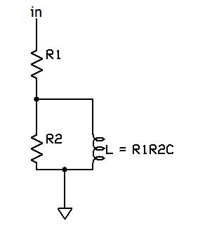
What’s the effect of the nonideality of the gyrator? For convenience, here’s the gyrator equivalent circuit again:

With the reactance of the inductive part being about 100k at crossover, the series resistance can be chosen; too low, and the opamp will be hard-pressed to supply current. Too high, and the series resistance becomes significant compared with the circuit impedances. For a “normal” opamp, 5k will be high enough to keep it out of trouble. At crossover, the 5k resistance will introduce about 0.4dB error. That I can live with.
Let’s now look at the rationale for and answer the objections to using a… gasp… IC opamp for the gyrator. Using the LC equivalent circuit above, the capacitor has a reactance of about 100k at the 110 Hz crossover frequency, as does the inductor. At these low frequencies and non-stressful service, it would be hard to argue against the notion that an IC will do fine. We worry more about the critical midband and treble. At 2kHz, the capacitor will have a reactance of about 5k, the inductor will have a reactance of 20M. The voltage divider ratio is -72dB, and that keeps increasing with increasing frequency. By 10kHz, the capacitive reactance is down to 1k, the driving end is presumably low impedance, and any deviations from ideal inductive behavior and any added noise are just buried. It’s still good not to tempt fate, so I wouldn’t cheap out and use a 741, but I am not convinced that anything better than (say) a TL072 will make much of a difference. Nonetheless, I used premium buffers in my unit (the now sadly-discontinued BUF03), and if someone wanted to realize the gyrator with a pentode or a very high transconductance triode, I wouldn’t think them crazy.
Putting it All Together
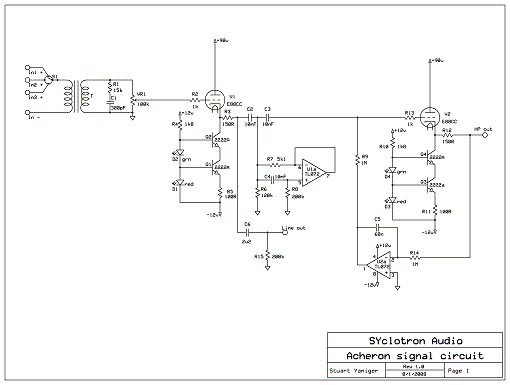
In order to be guaranteed that the LC filter works as planned, it must be driven with a low impedance and must be loaded with a known, constant, and (as a practical matter) high impedance. That means a buffer sandwich. Fortunately, it is quite simple to build a buffer that will not pollute or subtract from the desired signal, and can even contribute positively to noise reduction. I modestly point you elsewhere on this site to The Heretical as proof. So, our signal circuit, with all the necessary doodads done, looks like this: (click for a bigger image)


With noticeably degrading sound from DSP processors, I would gladly try something like the Acheron. 3-way stereo would be useful. If you produce and sell PCBs with assembly instructions, I would gladly give it a try and time my time, too.
DSP processors have long outrun the analog solutions, which is why this crossover is in a box in my garage and a Didden-modified DCX2496 is in my living room. Analog crossovers can still be fun, though…
If someone wants to do a PCB, I hereby grant universal permission- I don’t sell equipment or parts to prevent any conflicts of interest.
Thanks for your comment!