You’ll recall the data I posted here demonstrating that the voodoo hypothesis that dielectric absorption in coupling caps causes distortion in audio signals doesn’t stand up to either first principles or actual experiment. One of my Faithful Correspondents told me that the voodoo guys are now either ignoring actual data or suddenly changing their claim. “Coupling caps aren’t important, it’s the feedback cap that’s important!” Now, from a basic theory point of view, that makes no sense either- the important thing is that the corner frequency is well under the audio range, no different than a coupling cap. But since audio lore and self-promotion seem to be more durable than Keith Richards and Twinkies, I suppose it’s worth ten minutes of my time to give the wrecked and ruined claims another shin-kick.
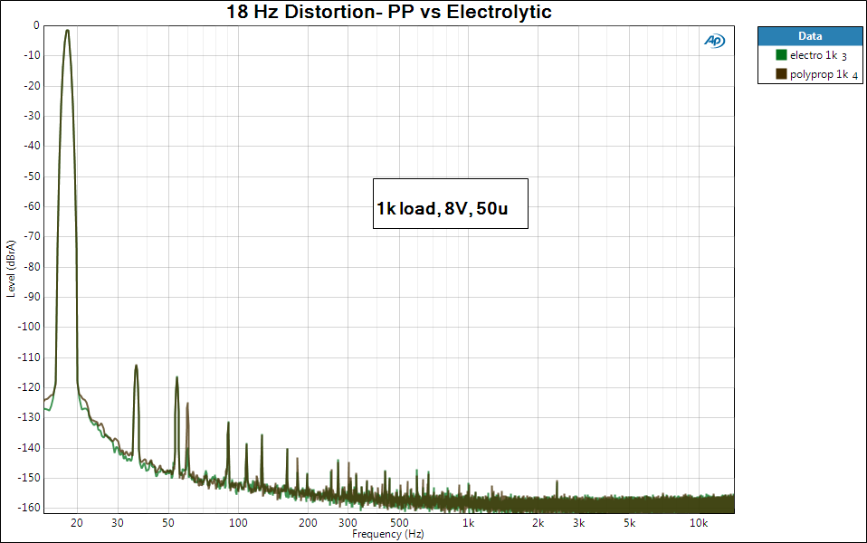
I grabbed the schematic for one of Nelson Pass’s designs, the Adcom GA555 power amp that has served me well over the past 3 decades. The feedback network is terminated with a 1k resistor in series with a 47u bipolar electrolytic cap- that corresponds to a corner frequency of roughly 3.4 Hz and seems pretty typical of the genre. I took the output of the trusty Audio Precision APx515 (set for 50R output impedance) and connected a capacitor to the input, then used a 1k resistor for a shunt. Nothing fancy about the resistor, it was a 2 cent special from Digikey. The capacitor was variously 50u polypropylene or two 100u electrolytics, back to back to form a bipolar cap. First I looked at the distortion spectrum of an 18Hz sine wave (that frequency chosen to allow the harmonics to be distinguished from 60Hz hum pickup).
As Gomer Pyle would say, “Surprise, surprise, surprise!” No difference except, again, the film cap’s bigger size equated to more hum pickup.
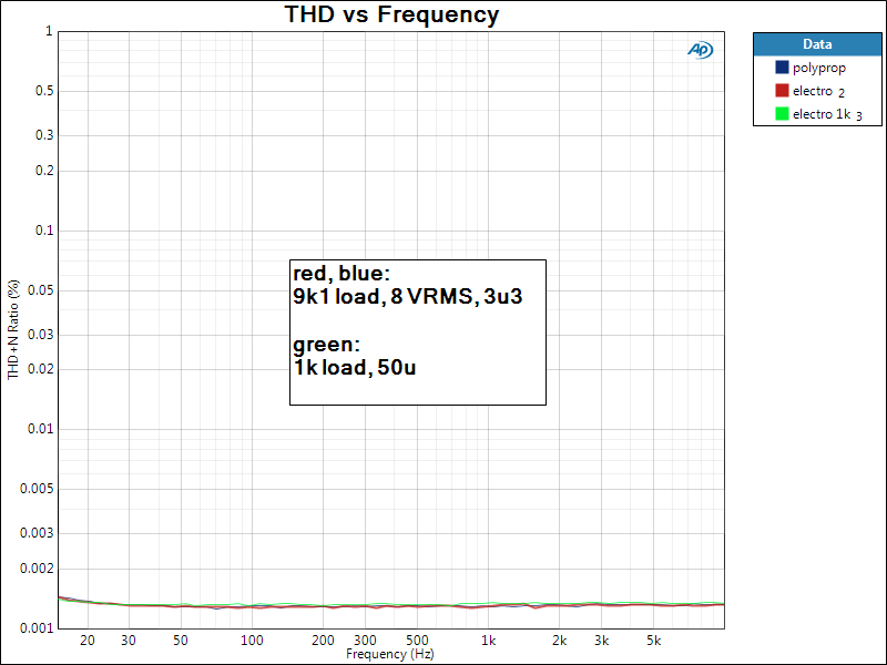
What about other frequencies? I ran a sweep of harmonic distortion versus frequency and it almost perfectly overlays with data I had taken with a slightly-under 10k load, also comparing an electrolytic with a film cap.
So under experimental scrutiny, the claim that a higher dielectric absorption capacitor has deleterious effects on distortion again proves to be untrue for coupling- and for feedback caps. The folks who insist that one needs anything special in these circuit positions have lots of assertion and exactly zero pertinent data to back up their claims. It’s sad that someone has to do something this basic to demonstrate what any competent designer already knew, but hey, that’s the world of “high end” audio.
It’s this simple: put the corner frequency below the audio band (which is necessary for flat frequency response anyway) and differences between non-pathological cap types goes away. The assertion that DA causes distortion in coupling caps and feedback caps not only makes no theoretical sense, it is demonstrably false.
Wonder where the goalposts will move next?
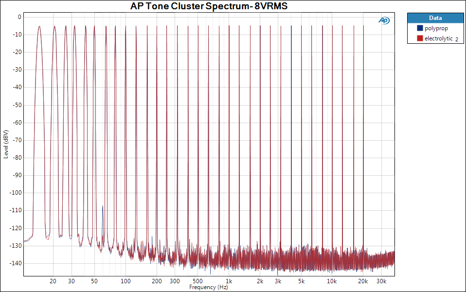
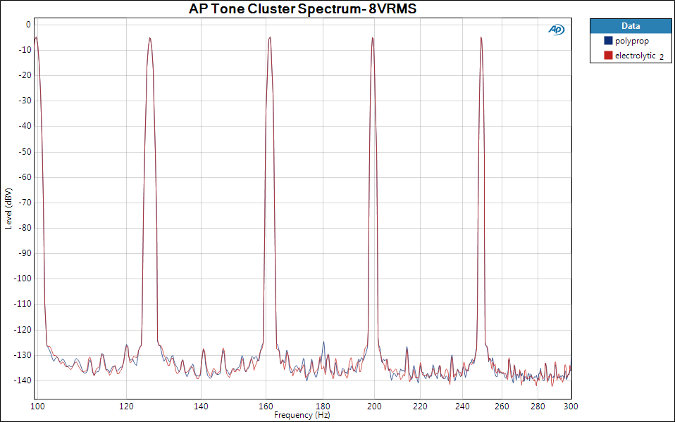
Addendum: at the request of one of the commenters, I’m adding another measurement, this a 32 tone cluster signal from the APx515 to look for intermods. Here’s the spectrum and an expanded view of a couple of tones to show the absence of intermods and sidebands. Note that the polypropylene is slightly inferior to the electrolytic in this application because of increased noise pickup.


Good job, Stuart, and yes, unsurprising. Pavel
Sy,
I am mostly with you, I am an EE so I must be,….
But to give the claims a chance – I suggest a test for IM
distortion. Non linearities may exist and produce IM.
I suppose that any problem cap may be more trouble in the
feedback position, so to kill two birds with one stone,….
P.S. “mostly” means I am trying to be nice to the nut cases.
Since I have not explored the topic myself – I try to keep and open mind. It is a struggle.
Cheers
Well, if there’s no difference in harmonic distortion at any frequency in the audio range, there would have to be something bizarre to show a difference in intermods- after all, if there’s a nonlinearity, harmonics would have to be generated. If I run my 42 tone cluster again, would that make you feel more comfortable? It’s pretty easy to do.
Oh yes comfort! Really Best.
LOL: I hesitate to waste your time, yet bizzare things sometimes happen. Actually I did not hesitate. I would do it myself – but my eShop is “under construction”. Soon to be ready – I will join you in the ‘myth busting’. My favorite is all the money people spend on cables. Now – perhaps there are some measureables with the cables, but really. The nutty thing to me is that people persist in cables, caps, lac-o-feedback etc – while ignoring one huuuuge common problem,…. that is the “Listening Room”. Which probably dominates everything else.
Meh, ten minutes at best. Happy to do it. Fourier works.
Anyway, see my comments in the first post in the series- swapping wires and caps is entertainment, where people can pretend that they have some creative input into their sound without the messy necessity of learning about perception and electronics/electroacoustics. Harmless in and of itself, but responsible technical folk need to speak up now and then to help slow down the enstupidation of the dwindling numbers of people who are doing audio as a past-time. The only people who really get annoyed are the many folks whose living depends on ignorance and a very few people doing this for fun who cannot fathom the possibility that they might be mistaken.
Gottit,
I have a friend who every so often makes some change to his system and declares a victory. “Now it sounds really great”!
I think it is the perception thing. “Your Brain on Music”,
https://www.amazon.com/Your-Brain-Music-Cognitive-Education/dp/197431328X/ref=sr_1_2?ie=UTF8&qid=1519151242&sr=8-2&keywords=your+brain+on+music&dpID=51f8AKu8vdL&preST=_SY291_BO1,204,203,200_QL40_&dpSrc=srch, along with sister writings – should be required reading for the Nut Cases.
AND then – why? – Our POTUS has proven that stupidity can’t be fixed, only used.
You can’t logic someone out of a belief that is not arrived at by logic.
Sy,
YES Belief is a REAL problem.
Accompanied by equating Truth with Facts – leads many astray.
So to all: Truth is .NOT EQUAL. to Fact.
Truth depends on “Faith”, Facts are subject to evidence.
Hence beware: Belief descends from Faith and is often upheld by Truth. But,…
Now the rant is over so you can relax.
I’ve added the requested data. The results were not unexpected.
The Heretical Preamp entirely eliminates the output coupling cap. Have you performed any “cap VS no cap” testing that might confirm whether the considerable additional complexity is worthwhile?
A good question! No, I don’t expect any performance difference, and I do show a cap-coupled version, but esthetically, some people are allergic to caps so a servo is a cheap and easy alternative. I could also rationalize it by pointing out the lower noise pickup versus a bulky cap, but the measurements show that noise, though measurable, is likely inaudible.
The elephant in the room is, of course, why use a tube instead of a FET, and again, the reason is esthetic, not functional. A FET would work just as well, especially now that MOSFETs with low drain-gate capacitance are cheap and readily available.
Sy, I have looked at your Heretical Preamp page and find exactly nothing! WTF? Is there a HTML issue?
Hey Daniel! The issue is a WordPress update that broke something or other (I don’t pretend to understand). This is the problem with a bunch of my older articles. My wife will be fixing it sometime in the next few weeks, all the content is still there, it just needs to be coaxed out- as best I understand it…
I will look forward to it Sy.
Just wanted to be sure you knew about it.
If it turns out that anything from the Heretical article has been lost, let me know. I’m pretty sure I have all the HTML pages, including images.
I started designing a similar circuit over a year ago, although I’ve always thought of it as simply auto bias, rather than a servo. My original paper design applied fixed bias to the grid and used an OPA445 to vary cathode voltage through a large value audiophile-grade choke. Yours does the opposite, varying the grid. There are pros and cons to each approach, and I honestly haven’t decided yet which is best.
Many thanks for your comments and for posting your work. I’m firmly entrenched in VT methodology for audio, and I believe the direct-coupled CF represents a nice step forward.
Hi SY,
Just to keep this wonderful discussion alive I am wondering if you have read these notes: https://linearaudio.nl/cyril-batemans-capacitor-sound-articles
I have not read them all, just a scan, but these and several other sources cause me pause.
Jack, we still have the content, we’re trying to fix the way WordPress tries to fetch it. Appreciate the offer!
Yes, and I referenced it in one of the posts. Bateman’s work was not really applicable to coupling caps, since he set up his tests to have significant voltage drop across the cap. In coupling, the voltage drop across the cap is low, unless the “designer” is someone not terribly competent and specifies a too-low value (i.e., a too high corner frequency).
Although most of the electrical stuff Bateman wrote about was correct- for the type of test he’s talking about- his comments on the material science and polymers are distressingly wrong and should not be taken seriously.
Good point, and of course all the audiophiles recognize how a component is used in circuit. A cap as load is a very demanding service. Really then, the best test is in the circuit it self.
Cheers
Dan
Thinking about it some more. (I know, what a concept!). Let us say, for the sake of discussion, that a non-linearity exists in the FB network, from a cap or any of the resistors, that generates an error signal of Verr = 1uV. So we have the attenuated output signal + 1uV error, going to the amp inverting input.
Since this error is not in the signal at the non-inverting input (Vin), it is amplified by the full open loop gain of the amp! So if your amp open loop gain is 60dB, a not unusual number, all of a sudden Verr appears at the output as a 1mV error signal. This is -80dB referred to, say, a 10V output signal.
My conclusion is that resistor non-linearity or capacitor dielectric absorption errors in the FB network may be minuscule (and your measurements show that they are), their effect is amplified by the amp’s open loop gain.
I wish I could think of a way to isolate and measure this error; I think it would be worthwhile to have more insight in this mechanism.